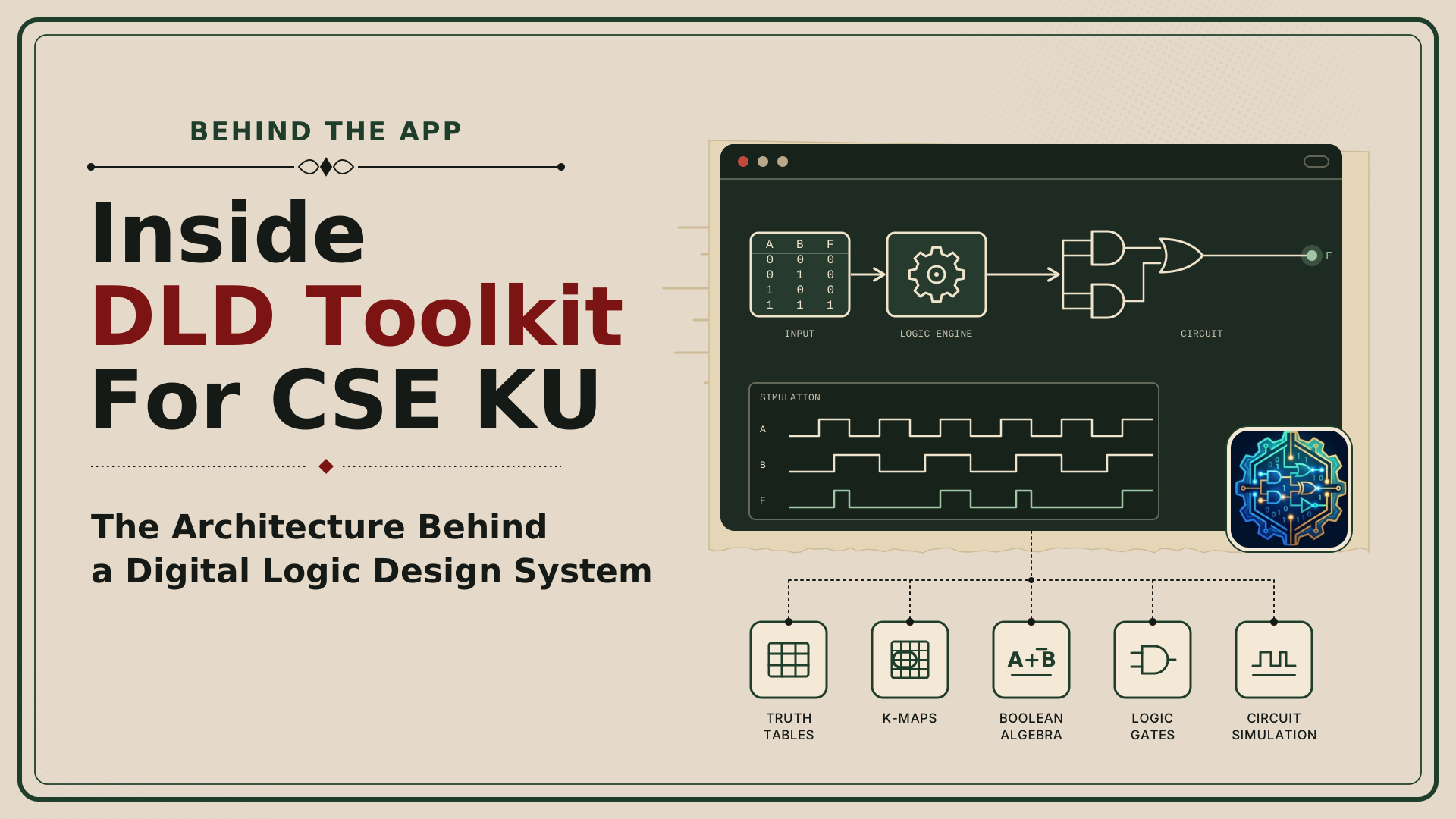
A digital logic design problem rarely ends with a Boolean expression. Before a function becomes a working circuit, it must pass through several stages: truth table generation, Karnaugh map analysis, Boolean minimisation, gate-level implementation, and simulation. Each stage represents the same underlying logic in a different form, but keeping those representations consistent is a significant engineering challenge. DLD Toolkit For CSE KU brings this entire workflow into one desktop application, allowing users to move from mathematical expressions to interactive circuit simulation without switching between separate tools. Developed by Taufiq E Elahi, a Computer Science and Engineering student at Khulna University, the project is built around C++17, Qt 6 Widgets, and a standalone computational engine called dld_core.
The project's most interesting engineering decisions are not simply the features it offers, but how it maintains correctness across different representations, simulates hardware behaviour, and controls computational costs. Version 2.1.0 emerged from a complete rebuild of an earlier prototype after an audit documented 16 backend defects and six GUI defects. That rebuild makes the project a useful case study in engineering software where mathematical correctness matters as much as usability. It also shows how a relatively focused educational application can involve problems commonly found in larger engineering systems, from module boundaries and performance optimisation to simulation accuracy and automated verification.
The Architecture: A GUI on Top of a Standalone Engine
The foundation of DLD Toolkit is a two-layer architecture with a deliberately one-way dependency. The Qt-based graphical interface handles windows, menus, circuit editing, visualisation, and user interaction, while dld_core performing the underlying calculations without depending on the interface. When a user enters a Boolean function, the GUI passes the expression to the engine and receives structured results such as a truth table, a minimisation report, a K-map model, or a compiled circuit. The engine never calls the GUI or relies on window state, which means the same computational logic can be tested independently and reused by the command-line companion, dld_cli. The core consists of 14 modules covering parsing, minimisation, circuit generation, simulation, routing, finite-state machines, diagnostics, and file handling, with the C++ standard library as its only engine dependency.
The architecture also separates circuit state from visual presentation through a controller called Document. It owns the circuit, undo history, selection state, live simulator, and cached wire routes, while views receive notifications when the circuit structure, simulation values, selection, or status messages change. This allows the schematic canvas and analysis panels to update according to their own responsibilities rather than relying on tightly coupled widget interactions. The canvas stores component positions in abstract grid units, with a separate view transformation controlling scale and offset, so zooming does not alter the circuit's underlying coordinates. User interaction is managed through explicit states such as moving, wiring, panning, selecting, and placing components, keeping editing behaviour predictable as the interface grows.
From Boolean Expressions to Consistent Results
A central challenge in the toolkit is ensuring that every component interprets a Boolean function in exactly the same way. The engine begins by tokenising the input into identifiers, constants, operators, parentheses, and supported keywords, then uses a recursive-descent parser to construct a syntax tree according to a defined operator precedence. The notation supports implicit AND, NOT operators, OR, XOR/XNOR, and minterm or maxterm lists with don't-care conditions. Rather than repeatedly interpreting the original text, later stages work with structured representations of the function. Parse errors also carry character positions, allowing the interface to identify where an invalid expression occurs instead of displaying an unhelpful generic error.
The project centralises bit ordering, an easy-to-overlook detail that can cause serious correctness problems. Every module treats the first variable as the most significant bit, using common helper functions defined in Logic.hpp. For example, minterm 5 in a three-variable function corresponds to binary 101, or (AB'C). The truth table, K-map, minimiser, circuit generator, and simulator all use the same convention, preventing the same input combination from being interpreted differently across modules. Truth-table evaluation is also bit-parallel: the engine processes 64 input combinations per pass using 64-bit words rather than evaluating each row individually.
Immutable, shared syntax-tree nodes allow repeated subexpressions to be reused, reducing redundant work when the same logical operation contributes to multiple outputs. The engine also caches expensive results when they can safely be reused. Minimisation results are stored per output, while wire-route caches are invalidated when component or wire movement makes them stale. These choices avoid repeating calculations that have not been affected by a user's latest action. The result is an architecture that treats consistency and performance as shared responsibilities rather than separate features.
Exact Minimisation and the Cost of Proving an Answer
Boolean minimisation is more demanding than finding an expression that happens to produce the correct output. A function may have multiple equally minimal solutions, and an educational tool benefits from showing those alternatives rather than presenting a single answer as though it were unique. DLD Toolkit uses the Quine–McCluskey algorithm to generate prime implicants, followed by an exact covering search to identify combinations that cover every required minterm. The engine identifies essential prime implicants, removes duplicate candidates, and uses branch-and-bound techniques to avoid exploring combinations that cannot improve the best solution already found. Solutions are ranked by term count and then literal count, with up to 16 equally minimal solutions retained.
POS expressions are obtained by minimising the zero-valued rows and applying De Morgan's law, keeping both major canonical forms within the same computational framework. Don't-care conditions can help implicants merge, but they do not have to be covered by the final expression. This matters because a valid minimum solution must cover all required output rows without treating unspecified rows as mandatory outputs. By encoding these rules in the engine, the application can reuse its minimisation logic across the truth-table, K-map, and circuit-generation workflows. The goal is not merely to produce a simpler expression but to make the reasoning behind that expression dependable.
There is, however, a fundamental trade-off between exactness and runtime. Prime-implicant generation can be relatively fast, while proving that a particular combination is the smallest may become expensive for dense functions with many candidate implicants. The project addresses this by imposing a search budget of two million steps. If the budget is exhausted, the engine can return a valid cover while clearing the exactness flag, allowing the GUI to warn that minimality has not been proven. In benchmarks on the development machine, difficult random eight-variable functions with roughly half their rows set to one took around 1.6–2.3 seconds in the worst cases. This is an important engineering distinction: producing a correct result and proving that it is optimal are different computational tasks.
Turning Logic into Interactive Circuits
Once a function has been analysed, the synthesis module translates its expression tree into gates and wires. Each expression node becomes a gate, while shared subexpressions can become shared gates with multiple consumers, avoiding unnecessary duplication. Variables can share inverter gates, and operations wider than the configured fan-in limit are split into balanced gate trees. The engine can also generate NAND-only or NOR-only implementations using De Morgan transformations and cancellation of unnecessary double inversions. For sum-of-products expressions, this can produce a NAND–NAND implementation that maps naturally to common digital logic building blocks.
Circuit generation also has to solve a visual layout problem. The engine assigns gates to columns according to their longest path from the inputs, then adjusts placement based on downstream consumers. Wires use orthogonal routes, with routing logic attempting to avoid component bodies and shared signal paths. When a generated netlist is ready, it replaces the document's current circuit as a single undoable operation, so the user can reverse the whole synthesis action instead of undoing each gate. This connects an abstract mathematical operation to a practical editing workflow without sacrificing the application's existing state-management model.
Karnaugh maps use a similarly explicit representation. The toolkit supports maps with one to four variables and uses reflected Gray-code ordering so neighbouring cells differ by one variable. Groups are derived from prime-implicant cubes, including cyclic groups that wrap around map edges. A group that covers the map's four corners is represented as an open-sided loop, reflecting the fact that the map's edges are logically adjacent. These details illustrate how the application must preserve the mathematical meaning of a function even when presenting it through a visual metaphor.
Simulation: Logic Values, Delays, and Feedback
A static truth table and a live circuit simulator answer different questions. Truth-table evaluation determines the output for a given combination of inputs, while interactive simulation must account for changing signals, gate delays, feedback paths, and sequential components. DLD Toolkit therefore uses two evaluation approaches. Its exhaustive evaluator uses two-valued, bit-parallel operations for truth tables, equivalence checks, and fault analysis, while its event-driven simulator supports live editing, timing diagrams, hazards, clocks, and sequential circuits. Keeping these implementations separate allows each to match the needs of its workload without forcing one evaluation model to handle every case.
The live simulator maintains a time-ordered event queue and schedules output changes according to gate delays. When events occur at the same simulation time, signal changes are processed together before affected cells are reevaluated and their outputs scheduled. This makes it possible to observe short pulses and glitches that a zero-delay, level-by-level evaluator would miss. The simulator also uses three-valued logic: 0, 1, and X, where X represents an unknown, floating, or uninitialised signal. For example, an AND gate with inputs 0 and X can still produce 0, because the known controlling value determines the output.
Feedback introduces additional complexity because a circuit may never settle. The engine uses strongly connected component detection to identify feedback loops during compilation, while the event simulator enforces an event budget to detect circuits that keep oscillating. Sequential logic includes behavioural D, JK, and T flip-flops, latches, registers, counters, and finite-state machines. The toolkit also models a gate-level master-slave JK implementation based on a 7476-style design, including its feedback and active-low preset and clear signals. These mechanisms make the simulator more useful for exploring real circuit behaviour, although they also increase the complexity of debugging and validation.
Reliability, Diagnostics, and Automated Testing
The toolkit does more than generate circuits; it can analyse ways they might fail. Stuck-at fault analysis tests stuck-at-zero and stuck-at-one faults on nets and fan-out branches, then simulates faulty versions of the circuit across input combinations. Identical faulty behaviours can be grouped together, and a greedy algorithm selects a compact set of test vectors that distinguishes the detected faults. Hazard analysis examines two-level Boolean forms for static hazards, identifies adjacent required minterms that lack a common covering term, and can add consensus terms to remove the corresponding logical hazard. The simulator can then replay single-input changes using gate delays and report output glitches. Together, these features connect Boolean theory to practical questions about fault detection and timing correctness.
Testing is particularly important because different representations can agree with one another while sharing the same bug. The project includes six automated test suites covering circuits, sequential logic, minimisation and K-maps, Boolean operations, library blocks, and GUI behaviour. The documented test run contains 60 cases and approximately 309,000 checks, including exhaustive verification, seeded random tests, round-trip conversions, and cross-checks between the two simulators. A 17-to-1 multiplexer is tested across all 4,194,304 input combinations, while independent checks compare minimisation results against brute-force methods for suitable small functions. GUI tests run offscreen, and the project also checks rendering performance at multiple window sizes.
The tests have caught practical defects that ordinary manual use might not reveal, including incorrect printed variable names, NAND-only synthesis producing AND gates, faulty FSM equivalence handling, and wires routed through unrelated gates. The documented suites pass on Linux, and the Windows build is cross-compiled with MinGW and tested under Wine 9.0, including GUI tests and installer checks. However, the project document does not report physical Windows testing or completed macOS testing, so those platforms should not be described as fully verified. This distinction matters: automated tests provide meaningful evidence of reliability, but they do not eliminate the need to test the application in its actual deployment environments.
Performance, Packaging, and Engineering Trade-offs
Performance depends on avoiding work that does not need to happen. Besides bit-parallel evaluation, the toolkit recompiles the circuit after edits, reuses cached minimisation results, updates only affected gates during live simulation, and avoids repainting the entire canvas for every minor interaction. The truth table formats visible rows on demand, while analysis panels calculate results when requested rather than after every keystroke. In the documented Linux release benchmark, generating a 16-variable truth table containing 65,536 rows takes about 0.38 milliseconds. An event-driven eight-bit adder processes 20,000 input changes in around four milliseconds, and canvas repainting at the tested window sizes takes approximately 1.3–4.3 milliseconds per frame.
Those measurements are specific to the documented development machine and should not be interpreted as universal performance guarantees. The project also has deliberate limits: truth tables support up to 16 variables, minimisation up to 12 variables, exhaustive circuit evaluation up to 24 inputs, and automatic GUI generation up to 600 components. These boundaries help keep operations manageable, particularly when an exact algorithm's cost can rise sharply with problem size. One documented improvement still on the roadmap is moving expensive minimisation into a background worker with progress reporting and cancellation. That would help prevent a difficult calculation from temporarily blocking the GUI.
Qt 6 Widgets was chosen to combine standard desktop controls with custom vector-based gate drawing. Alternatives such as native Win32 drawing, Dear ImGui, SDL/SFML, and Electron were rejected for reasons including portability, widget support, high-DPI handling, application overhead, and implementation complexity. The application uses CMake, a Windows installer, and a plain-text .dld format for circuits, alongside PNG schematic exports and VCD waveform exports. Version 2.1.0 operates fully offline, without accounts, telemetry, or network access, and the documented Windows installer is unsigned, meaning Windows SmartScreen warnings may appear. The project proposes future features such as update checks, circuit sharing, classroom assignments, additional export formats, and a browser version, but these are roadmap items rather than capabilities of the current release.
Conclusion
DLD Toolkit For CSE KU demonstrates how a specialised desktop application can benefit from the same architectural discipline used in larger software systems. Its standalone C++ engine separates computation from presentation, shared logic conventions keep mathematical representations consistent, and specialised evaluators handle exhaustive analysis and time-dependent simulation. Exact minimisation provides strong educational value, while bounded search makes the computational limits visible instead of silently claiming optimal results. Automated tests, performance measurements, and explicit platform caveats help distinguish verified behaviour from assumptions about what should work. The architecture is not without trade-offs: exact search can block the interface on difficult inputs, the GUI imposes practical size limits, and some deployment and online features remain future work.
The broader lesson is that correctness, usability, and performance cannot be designed independently in an engineering tool. A visually convincing circuit editor is not enough if its simulator disagrees with its truth table, and a mathematically exact engine is not enough if expensive operations make the interface unresponsive. DLD Toolkit addresses these concerns through clear module boundaries, specialised algorithms, cached computation, explicit simulation semantics, and systematic testing. For developers building similar technical applications, the project offers a useful reminder: the quality of an interface depends heavily on the architecture beneath it, especially when the application must turn abstract rules into results users can inspect, test, and trust.
Did you enjoy this dissection?

Discussion (0)
No comments yet. Be the first to start the engineering discussion!